Lightweight HO Scale Modular Layout Tables
Designed by Stu Dom
For Use by MPRR Club Members
January 17, 2006
Table of Contents
4.3.2.2 Module Leveling Adjusters
4.3.2.5 Leg Support Box (K1, K2 & K3)
4.4.1 Protective Barrier - Plexiglas (P)
4.4.2.2 . Support Details (I, J & M)
List of Figures
Figure 1 – Assembled Table in Setup Condition
Figure 2 – Assembled Table Ready for Transporting
Figure 4 – Frame Corner Joint Detail
Figure 5 – Frame with Top Support Inserted Into Frame (Top View)
Figure 6 – Frame with Top Support Inserted (View from Bottom)
Figure 7 – Detailed Drawing of Frame – Front/Back (A)
Figure 8 – Detailed Drawing of Frame – End (Part B)
Figure 9 – Detailed Drawing of Frame – Cross Brace (C)
Figure 10 – Leg Support Box Attached to Module Corners
Figure 11 – Leg Assembly (Detailed View)
Figure 12 – View of Legs in Up Position
Figure 13 – Leg Support Details – Box Sides/Middle (K3)
Figure 14 – Leg Support Details – Box End (K1)
Figure 15 – Leg Support Details – Box End (K2)
Figure 16 – Leg Bracket Details (E)
Figure 17 – Protective Cover & Plexiglas Support
Figure 18 – Plexiglas & Protective Cover Support (I, J & M)
Figure 19 – Protective Cover Removal Sequence
Figure 20 – Protective Cover Sides (D)
Figure 21 – Bottom of Cover Showing Provisions for Plexiglas Storage
Figure 22 – Inside of Protective Cover Showing Plexiglas in Stored Position
Tables
Table 1 – Bill of Materials for Various Size Modules
1 Background
The Mohegan-Pequot Model Railroad Club has active transportable layouts in many scales. However, HO scale modeling has the largest following within the club, and has routinely set up layouts as large as 72 by 42 feet that have included up to 70 separate module tables and linear track lengths of over 300 feet when the layout is configured in a “U” shape. Bringing all of these modules together represents a monumental task for our transportation department who generally range in age from about 25 to 85, with an average age about 50.
Designs for the module tables have generally followed the philosophy of building a platform using standard dimensional lumber for top and sides, then trying to determine the best way to attach legs to the table. In many cases, legs were such an afterthought that they have been separate from the modules, which represents additional transportation issues. Several years ago, I designed a set of 9 modules, known as the passenger station that set out to improve on the module design by ensuring that the legs were always attached to the modules. This design was used to create modules of 4 and 8 foot lengths and 39 inches deep, and turned out to be extremely heavy (the largest weighing in at well over 150lbs.
Remembering that weight is becoming very important to those of us who are out of shape and over 60, I decided to design a lighter weight module concept that could be used by club members to provide a strong and stable platform, with attached legs and a removable top that would protect the scenery and track work. The first thing that I did was to get the club to accept modules that had a length of 4 or 6 feet, as opposed to the club standard of modules that had lengths of multiples of 4 feet, which was readily accepted by the club module committee. Thus, there would be no more 8 foot modules in our modular design; they would be either 2, 4 or 6 feet in length. This had to result in a lighter module, if I did nothing else.
2 Design Approach
The design started by researching the techniques used by others, namely the other members of the club who model N and ON3 and G scale and articles in model railroad magazines. I found that our N and ON3 scale modelers use foam, thin sheet plywood and tapered legs in their design. Their designs are easily transported because they are extremely light. So, I have a start.
Knowing this, I designed a module that made extensive use of one half inch thick poplar wood for the frame, which I planned down myself, since it is extremely light and strong. I selected 1 inch foam for the top surface of the module and used 1/8 inch Baltic birch plywood as a support for this foam. I then conducted a study of legs and determined that, while more costly, aluminum legs would provide a strong support that was several pounds lighter than any wood alternatives. I built a prototype module of 4 feet in length by 3 feet in depth and found that the module, with legs, weighed in at less than 30 pounds. Thus, I thought I had a good design that I would use to form the basis for construction for my future modules.
Having seen this prototype module table design, I received much interest from the many of my fellow club members to build modules for them since they lacked the tools and possible woodworking knowledge to build modules of this design. There was so much interest that we all agreed to pull our resources together and have a mass building of modules, using the woodworking tools and facilities available at my home and the home of another member. However, I had to first modify my design a little to accommodate several conditions that I hadn’t planned on with my design.
First, I had no intention of creating several hundred board feet of ½ inch poplar lumber for such this project. This would require planning down a lot of wood, and I didn’t believe the pain was worth the gain, so I selected ½ inch birch plywood for the frame, rather that the poplar lumbers. This only added less than two pounds to the weight of the frame, which was a good compromise.
Second, since many of the club members wanted 6 foot modules, I needed to change my design to make use of ¼ inch Luan instead of 1/8 inch thick Baltic birch plywood, since the later was only available in our area in a 5 by 5 foot sheets. Again, an added weight, but a necessity.
Third, since tops were important to overall transportation and protection of the modules, I had to develop a removable top for the modules.
The resulting design is shown in the following paragraphs. But, the end result was that we, about 8 of us, managed to build a total of 31 modules in 3 weekends in May and June of 2005 using this design. Since then several more modules have been constructed using similar construction methods, and I have requests from several members to have another module build session. Now, if we could manage to get the track and scenery on the modules we have already built, life would be good.
3 Completed Module Table
As noted before, modular tables were constructed in both 4 and 6 foot lengths, and the width varied from 30 to 36 inches. However, for demonstration purposes in this report, the module is 6 feet in length and 36 inches deep. The height of all module tables to the top of the mainline rail is 40 inches plus or minus 1-1/2 inches to accommodate variations in the levelness of the floors in the facilities that we set up in. The completed table in its setup condition is shown in Figure 1. The threaded inserts for the legs that allow for leveling of the table are not shown in this picture of pictures to follow.

Figure 1– Assembled Table in Setup Condition
As can be seen from Figure 1, the legs have been folded down and both cross braces and angle braces have been used to stabilize the legs. A holder for Plexiglas is shown on the front side of the module table. A similar holder is also attached to the back to provide support for the top when it is installed. The top is a piece of construction foam (1” thick) that sits in the box formed by the sides. The track roadbed would be attached directly to this top surface.
The completed module table in the transportation mode is shown in Figure 2. Notice that the legs have been folded up into the table and a cover has been placed on the top to protect the scenery and track. Specific details of the construction will be discussed in the following paragraphs.

Figure 2– Assembled Table Ready for Transporting
4 Construction Details
4.1 Materials and Dimensions
As indicated before, modules have been built in several sizes, depending on the individual module builders needs. Such things as amount of track and scenery desired, ability to carry, and space available for transportation and storage are the key decisions that one has to make to establish modules size. As noted before, lengths were limited to 4 and 6 feet for handling purposes. In addition the depth for all modules was 30, 32 or 36 inches, although other sizes could have easily been accommodated.
Table 1identifies the dimensions of all parts used in module construction. One could easily determine the dimensions of these parts if other module depths were used, based on the values in this table.
4.2 Frame & Top
4.2.1 General Description
The frame is constructed of ½” birch plywood. The completed frame is shown in Figure 3. The perimeter sides of the frame are 4 3/8” high, and the cross braces are 2 5/8” high. The height of the perimeter sides and braces allow for the use of tortoise switch machines mounted on their sides to and for about for 1/8” of additional clearance at the bottom. A ¼” x ¼” groove has been routed into the perimeter sides, 1” down from the top to allow for insertion of the table top support, and on top of that the foam top surface. Note also that the cross supports are set into dadoes in the front and back (1/2” wide by ¼” deep), and that they have notches at the ends to accommodate the legs when they are folded up into the top. More details on the legs will be provided in paragraph 4.3. Also note that the cross supports have holes drilled into them to allow cables to pass through the layout from one end to the other.

Figure 3– Completed Frame
The joining technique used at the corners is shown in Figure 4, where the sides or ends of the module table are on the left and the front/back of the table is on the right side of the figure. This type of joint is relatively easy to make with a router or table saw, and eases construction – especially important for mass production. However, a butt joint would work and provide adequate strength given the box structure that is formed by the leg pocket that will be discussed in paragraph 4.2.2.

Figure 4– Frame Corner Joint Detail
Note also the groove in the frame pieces to allow for insertion of the plywood support plate, that is shown installed in Figure 5& Figure 6. Insertion of this plywood piece must be made from the front or back prior to final assembly of the front or back part, since the dimensions of the plywood support piece are larger than the inside dimensions of the frame. Be careful to set the dimensions of the plywood support to allow about 1/16” clearance on all sides or there may be problems during the assembly process. Zero or negative clearance fits are always a no-no. All joints used in this design are glued and nailed (a pneumatic nailer is lifesaver is you have one).

Figure 5– Frame with Top Support Inserted Into Frame (Top View)

Figure 6– Frame with Top Support Inserted (View from Bottom)
The length of the front and back frame pieces will be either 4 or 6 feet, depending on which size you choose to build. The length of the ends and cross braces will be the desired depth of your module minus ½”. Note, for 4 foot modules only 3 cross braces will be needed, not 4 as shown on the previous figures. The foam insert for the top will be 1” less than the final dimensions of module table. In our mass construction project we used Liquid Nails adhesive made for attachment of construction foam, but white or yellow wood glue could be used provided you can hold the top in place while it dries.
4.2.2 Details
4.2.2.1 Front/Back (A)
As can be seen from Table 1, the two lengths of modules included in this design were 4 and 6 feet. Each of these is similar in construction as they both have dadoes for the end pieces, dadoes for the cross supports and a dado cut for the plywood top support. Details of these pieces are shown in Figure7.

Figure 7– Detailed Drawing of Frame – Front/Back (A)
As noted in 4.2.1the joints used for this assembly could have been simple butt joints. However, dadoes were used for all joints to ease assembly, ensure a good fit between parts, and retain perpendicularity between the assembled parts. All dadoes for these parts have been made on a table saw, with a dado blade set for ¼” width by ¼” depth.
4.2.2.2 Ends (B)
The ends of all module designs are similar. Only the length is changed to accommodate the various module depths. A representative drawing of an end piece designed for a 36 inch deep module is shown in Figure 8. Again, as was done for the front/back piece, ¼” by ¼” dadoes were used for all cuts.

Figure 8– Detailed Drawing of Frame – End (Part B)
4.2.2.3 Cross Braces (C)
Of the parts that make up the frame the most complicated to product is the cross brace. There are several features in the cross pieces that make the cutting more exacting, as shown in Figure 9, which shows parts for a 36 inch deep module. The important features of the design for other sizes are exactly the same as that show for the 36 inch deep module – only the length would be changed. The most significant of which is the fact that there are 3 distinct types of cross brace pieces needed for a 6 – foot long module, while only 2 unique pieces are needed for the 4 – foot modules. Each piece has a ¼” by ¼” rabbit at each end to allow insertion, gluing and nailing of the piece into the front/back pieces.

Figure 9– Detailed Drawing of Frame – Cross Brace (C)
The most distinctive feature in all cross braces is a notch on each end. These notches are needed to allow the legs to be positioned up into the module while being stored or transported. A jig saw or saber saw can be used to make this cut, as the finish and accuracy of this notch is not very important. The second most observable feature is the holes that have been drilled into the cross brace that allow for passage of wiring and cable harnesses. The sizing and spacing is arbitrary, but drilling holes prior to assembly will ease the job later. We determined, however, that at least one whole in each piece should be about 1” in diameter to allow the DC cable harness plug to pass through, as opposed to the ¾” shown. Try however to keep the holes near the center of the cross brace to improve the stability of the assembled table.
Other than the overall dimensions, the most exacting feature of the cross brace is the location of the dado slot near the ends of the of the Type 1 and Type 2 pieces. These ½” wide by 1/8” deep dadoes are required to accept the bracket (E) for the leg. There are two locations for this slot due to the need to have the legs at different spacing on each end to support stowing the legs in the up position for transportation and storage. This can be seen in Figure 11and Figure 12. This slot could be eliminated from the design and (E) reduced in length if you wish, but alignment of this cross brace will become more difficult during final assembly.
1.1.1 Top (G & O)
The top consist of two parts; (1) a top support piece (G), that is simply a ¼” piece of Luan that slides into the frame assembly during construction, and (2) a 1” foam piece (O) that actually forms the top surface of the module. An overlay of plywood could be used as a protective cover over the entire module could be used, if desired, but the overall weight of the module could increase by about 25%. The builder needs to determine if this weight increase is worth the gain in stability and durability. I do not believe it is necessary at this time, but may find I wish I had this after I actually start laying roadbed and track.
There are no unique features to either, except to ensure that the top support piece is slightly smaller in all dimensions than that need to fit in the slots included in the front, back and ends of the module. In addition, this piece should be continuous and should be exactly square, and this will be used to square up the frame assembly during assembly. The foam piece simply slides into the recessed region of the module once the frame is assembled, and must be glue onto the top support piece.
1.2 Legs
1.2.1 GeneralDescription
Legs are attached to the module table using a special box-like structure as shown in Figure 10. This box-like structure should be pre-made and inserted into the module frame during assembly. This structure provides a very strong pivot for the legs, and reinforces the module table frame.
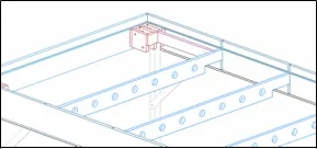
Figure 10– Leg Support Box Attached to Module Corners
A more detailed view of this structure is show in Figure 11, along with the leg and leg support bracket, with the leg shown in the down position. The box-like structure is designed to be used in all of the corners, although there is a slight difference in the assembly process for each corner. This will be discussed further in later paragraphs.
The protuberance on the right allow for connection of the leg support bracket, and must be sized to fit between the box-like structure and the first frame cross support, that has a mating slot as seen in Figure 10. In the case of our construction process, where we made both 4 and 6 foot modules I set the first cross brace to be exactly the same distance from the end so that this piece could be made to the same dimension for all modules.

Figure 11– Leg Assembly (Detailed View)
Brass inserts were used to provide a threaded connection point for the through bolt that was used as a pivot point for the leg. An additional bolt was also used diagonally opposite the pivot point screw onto which a nylon insert lock nut was used to adjust the tension on the center plate that was designed to be floating. This locking device was also used on the pivot point screw. The purpose of this tensioning device was to allow for some slop in the manufacturing process and allow a controlled pressure to be applied to the pivoting leg, which will improve stability. It is this feature that caused the 4 corner leg pockets to be assembled differently from each other. This is best shown in a top down view of the legs (now in the stowed or up position) when attached to the module as shown in Figure 12. Again, this design feature made it possible to make large numbers of leg support pockets with the minimum number of different parts – a plus for mass production.

Figure 12– View of Legs in Up Position
As you can see from Figure 12the legs on one end must be positioned inside the legs of the other end to allow the legs to fold past each other. Again, no interference is allowed in this design. All of the box-like structures have the same dimensions but there are important differences to note for each position. First, because of the above mentioned positioning of the legs, there are two distinctly different box pieces to allow attachment of the leg bracket support structure. This difference would be avoided if one were to use a butt joint for this connection rather than a rabbet joint. For the purposed of mass construction, I believe that the positioning of this bracket would be better controlled using a rabbet joint rather than a butt joint. Secondly, since brass threaded inserts were used for the pivot bolts, the boxes need to be handed. That is, the opposite corner boxes are the same but different from the other two boxes.
The cut dimensions for all boxes are the same. Dimensions for all parts are included in Table 1. The hole located in the side and middle pieces of the box are at the same location, but the plate that fits to the outside of the boxes must be sized to fit the threaded insert, while the others need to have clearance for the through bolt. We used 5/16” bolts for these boxes.
1.2.2 Details
The legs consist of 3 distinct pieces; (1) the legs themselves - aluminum for this project, (2) a leg support box or bracket, and (3) various braces and stiffening pieces. The primary function of all of these pieces is to provide a strong and stable support for the table that easily fold-up into the module for stowage and travel.
1.2.2.1 Legs (R)
Square 1 inch by 1 inch thin wall (1/16 or 0.0625 inches) aluminum tubing was used for the leg material. This material is light weight, strong, relatively easy to find, and can be cut with a hacksaw, although for this major project we ordered the material already cut. Holes (1/4”) were drilled in the aluminum stock at locations of 1-7/8” and 11-1/8” from one end to accommodate bolts that would act as a pivot point for the leg and attachment of the leg brace.
1.2.2.2 Module Leveling Adjusters
A threaded insert was used at the other end of the leg, where a 4 inch carriage bolt was threaded in to allow for adjustment of module height. These threaded inserts proved to be somewhat hard to find, and there are many versions that seemingly do the same thing, but there is a difference in quality so one needs to review the options carefully. One could also make an insert out of wood and use a T-Nut as I did on my demonstration module, but this is very time consuming.
1.2.2.3 Leg Brace (Part Q)
The leg support bracket is made of flat bar aluminum stock (1” wide by 1/8” thick). The length of this can be found in Table 1. A whole (1/4”) is drilled in each end of the bracket ½” in from each end to allow insertion of a pivoting bolt on the leg, and attachment to a threaded stud on the leg bracket when the module is standing.
1.2.2.4 Cross Braces (F)
Cross braces were placed between the folding legs of each end to stabilize the module against front to back motion. Since these cross braces are used to support attachment of a latch to hold the leg in the stowed position, the positioning of these legs should be flush with the face of one of module frame cross braces.
1.2.2.5 Leg Support Box (K1, K2 & K3)
A general description of the leg support assembly, this section provides detailed drawings of this assembly. Refer to Figure11for an assembly drawing of the assembled box. As noted in Table 1all pieces have been fabricated out of ½” Baltic birch plywood for strength and uniformity of material, although regular birch plywood could have been used. The following sections will provide detailed drawings of the 5 pieces that make up the support box assembly.
1.2.2.5.1 Box Sides/Middle (K3)
There are two types of box side/middle parts as shown in Figure 13. The only difference between these two types is that Type 1 has a 3/8” hole designed to accept a ¼” brass threaded insert, and type 2 is drilled for clearance of a ¼” bolt. One could have used a ¼” T-Nut in lieu of a brass threaded insert, but the top of the T would have to be recessed into Type 1 part so that this face could adjoin the front/back frame with no gap. In addition in order to allow the center piece to be adjustable, one should sand or remove about 1/64” of material from the left and right sides of the Type 2 piece after drilling the holes.

Figure 13– Leg Support Details – Box Sides/Middle (K3)
1.2.2.5.2 Ends (K1 & K2)
The end piece that adjoins the frame end is a rather simple piece, but has a dado on each end to allow ease of assembly, and a wider dado slot in the middle to allow the middle (K3) to slide a little to allow a tension adjustment for the leg. This is shown in Figure 14.

Figure 14– Leg Support Details – Box End (K1)
The opposite end is complicated by the fact that the leg support bracket must be positioned to be under the leg to allow the support brace to be connected when the legs are up. This can be seen in Figure 12. The details of these two pieces are shown in Figure 15.

Figure 15– Leg Support Details – Box End (K2)
1.2.2.5.3 Assembly
With all of these parts, care must be exercised in assembling this leg support box assembly. Because of the differences in leg position on the relative to the corners, and the need to keep the leg insert on the outside, or against the front/back pieces, there are four distinct assemblies for each module.
1.2.2.6 Leg Bracket (E)
This item provides a point for which the leg brace can be attached when the legs are in the folded down position. It connects between the leg box assembly and the first frame cross brace. It is a simple cut piece of wood with a hole drilled into it to put a stud for attaching the leg brace. Other than needing to fit snuggly between these two pieces, the most critical dimension is the placement of this hole.

Figure 16– Leg Bracket Details (E)
1.3 Protective Features
1.3.1 Protective Barrier - Plexiglas (P)
Plexiglas us used on the front of the module for two reasons: (1) keep little fingers for the viewing public from inadvertently damaging the scenery or trains, and (2) to keep our smooth running trouble-free rolling stock from hitting the floor. For this module design it was decided to use 1/8” Plexiglas since it is relative light. See Table 1for dimensional details of this material. In addition, it was determined that the best way to attach this Plexiglas to the module was to slide it down into a slot, or Plexiglas holder, when set up, and remove and store the Plexiglas either in the protective cover, Section 4.4.3, or a separate club provide storage box while transporting or storing the module. This has been successfully done in the past, although care must be taken in handling the material as it scratches relatively easily.
1.3.2 Support
1.3.2.1 Features
Support is provided for the Plexiglas on the front of the module, and the same design is used to support the protective cover. A 3-D drawing of this feature is provided in Figure 17. This support consists of a spacer slightly larger than the thickness of the Plexiglas, a cover piece to provide support, and a piece on the corner to act as a stop for the Plexiglas and protective cover, protection for the corners of the module, and a surface for the modules to slide on when transported or stowed on end.

Figure 17– Protective Cover & Plexiglas Support
If you were to observe this same point with the protective cover in place it would look very similar, with the side pieces for the protective cover positioned in the same slot as for the Plexiglas
1.3.2.2 . Support Details (I, J & M)
The Plexiglas is supported vertically with thin blocks of wood (1/8” Baltic birch) (J) that is slightly thicker than the Plexiglas. In the lateral direction the Plexiglas is supported between the frame front/back (A) and a Plexiglas cover (I). A protective piece (M) is used at the end for the reasons indicated in paragraph 4.4.2. Figure 18shows the details of these parts as if looking from the inside of the module through the non represented front frame piece. The darkest green piece on the left end is the Corner Protector piece (M), the horizontal green piece is the support piece (J), and the piece behind the Plexiglas is the Plexiglas cover (I). It should be noted (I) consists of multiple smaller pieces as opposed to one long piece, with separation between them to allow dirt that falls down into the slot to fall through.

Figure 18– Plexiglas & Protective Cover Support (I, J & M)
The dimensions for all pieces are identified in Table 1. In our module construction project we rounded the corner of the (M) so that it didn’t catch on clothing or did not restrict sliding movement of the modules when stored vertically. Another detail of the arrangement is to align the bottom of (M) with the bottom of the front/ back (A), then align the Plexiglas cover (I) with the top of (M), and, lastly, align the bottom of (I) with (I). Also observe that the Plexiglas must be notched at the ends to allow the Plexiglas to slide down into the slot, Figure18.
1.3.3 Protective Cover
1.3.3.1 General Description
During storage and transit, modules can be damaged easily. Over the last several years the club has created and installed protective covers on its newest modules, which have been very effective in reducing damage. Figure 2shows the cover in place and ready for transport or storage. However, unlike our previous efforts whereby the cover was the entire size of the module surface and presented a significant storage problem themselves, it was decided for this project to create the cover in two parts, hinged in the middle to allow folding of the cover and easier storage. This is depicted in Figure 19, where one-half of the cover has been lifted from one end of the module and folded back onto the other half – the entire cover removed for temporary storage. This cover is attached to the module during transit with 4 screws that can easily be removed when desired.

Figure 19– Protective Cover Removal Sequence
Details of the specific parts used in this cover are specified in Table1. Standard captive pin butt hinges are used to connect the two pieces together. Cross braces are used in at the ends of each section for strength and to allow the hinges to be attached to the top surface. And the Plexiglas is stowed in the top for transit.
1.3.3.2 Details (D, H & N)
1.3.3.2.1 Front & Back Pieces (D)
There are two unique aspects of the front & back pieces (D). One is that they are notched at the ends to allow for clearance at the corner protector (I) when inserted. The other is that there is a rabbet running the length of the piece to allow insertion of the cover into the slot created by the support and cover pieces (I & J). Note that there are two types shown with are identical except they are reversed from one to the other. There are actually two additional (D) parts that are the same as those shown, except they do not have the dado near the top for support of the Plexiglas. Also note that the lip that remains at the bottom must be thinner than the slot provided by the protective cover support, so make sure that this lip is < 1/8”. The overall dimensions of (D) are shown in Table 1, but the details shown on Figure 20are identical for all module sizes.

Figure 20– Protective Cover Sides (D)
1.3.3.2.2 End & Middle Braces (N)
The primary purpose of (N) is to provide support for the top at the ends and give a backing for the hinge support. A relatively strong and straight wood is needed to provide this support. An additional feature of these pieces is to support the Plexiglas while storing and transporting the modules. As noted above, a dado has been cut into (O) pieces on one side of the top. A similar notch is also provided in (N) to allow the Plexiglas to be supported within the depth of the (N) parts and held in with clips. An optional clip is also provided in the middle of the cover to support the Plexiglas in the middle. These notches and optional support are shown in Figure 21.Figure 22is a similar picture showing the Plexiglas in place for storage.

Figure 21– Bottom of Cover Showing Provisions for Plexiglas Storage

Figure 22– Inside of Protective Cover Showing Plexiglas in Stored Position
The notches at the end of the (N) pieces are 3/16” deep and 4-7/8” long. The optional Plexiglas center support is the same thickness of as (N), but need not be more than 1-1/2” long and has a notch 3/16” deep and ¾” long. The holding pieces (no number) can be of any length but the width can be no more that the width of (N) so that the two in the middle can be rotated passed each other. These pieces are simply held on to (N) with a #6 by 1-1/4” wood screw that has been countersunk to be flush with the top of the piece.
1.3.3.2.3 Top (H)
There is nothing unique about the top (H). The dimensions of this piece are shown in Table 1, and the top is glued and nailed (or screwed) onto pieces (O) and (N).
1.3.4 Frame Runner (L)
A solid wood runner is provided at the bottom of the frame front/back (A) rails to provide a sliding surface for loading when the modules are loaded or laid on the ground. Otherwise, the plywood sides would deteriorate quickly as plywood is not made to be slid or laid on its edge.
2 Conclusion
The plans developed herein have been used successfully for a significant club building project. These plans were made to allow for ease in assembly and cutting since multiple modules were built at the same time. Some of the construction techniques could be simplified to avoid the need for shop grade woodworking tools. However, in most cases a router, table saw with a good fence and a chop saw is all that is needed to do the job. Ensuring that all cuts are perfectly square will go a long way to achieving a high quality and long lived modular table. Do not skimp on the quality of the material as this will only lead to premature problems like loose joints, lack of rigidity and warping.
One other thing to remember is that you should take your time and do it right initially. You will likely be investing less than 10% of your total cost of the module in the bench-work, and if it fails to provide the needed rigidity, strength and straightness, the other 80% of your time and effort will be wasted. Too often I have seen the bench-work fail or deteriorate long before the track, wiring and scenery fails to operate properly or begins to look bad. The worst part about the bench work is that it is far more difficult to repair than the other things, so do it right the first time.